Showing posts with label Golf Rad Conversion. Show all posts

May 14, 2011

Updates and SU Spring Info

I have moved the reservoir to the firewall until the new header tank arrives from Merlin Motorsport. Conversion looks much cleaner now and with the new tank should look even more at home. Thermostat cover has been drilled and tapped 1/4NPT with 1/4 barbed fitting to purge air from the high point in the system.

Megajolt components permanently mounted and wires wrapped. Now just to remove the induction unit for the tach and get the tach out feed on the Megajolt working.


Tank Mount Position and Megajolt vacuum line

Reservoir Plumbing, tee'd into manifold heater and take off from
 the thermostat cover which is the highest point on the motor.

Megajolt takeoff using a .030" MIG Tip

EDIS module mounted properly to firewall,
nearly out of site from above

Crank Sensor Adjusted

Rad Plumbing

Dirt Road Life

STD 4.5oz HS2 Springs shortened to 3.625" for 2oz preload
(I have added this to my previous mod post)

March 19, 2011

Golf Radiator Conversion Running

I have added a new page covering my conversion but I will add it to my blog roll as well. The version found here will be kept up to date.

I did this swap as a means to affordable put a readily available alloy rad in place of the stock rad. I wanted to improve the systems cooling capacity and reduce weight on the front end of the car.


Components needed:
  • Mk3 Golf Rad
  • GT6 Thermostat Cover
  • 1-1/4" Dia Rad Hose Elbows ~100-110deg x2
  • Vacuum Cleaner Piping (Yes from a central vac or equiv.)
  • 4 additional rad hose clamps
  • 1" x 1/8" x ~28" Aluminum Stock
If the radiator is from a scrapyard donor it will have a built in thermostat to control the fans. You can use this to directly switch the fans on or use it to trigger the relay(s) as I have done.


The dimensions for the golf rad. It is also 1.25" in thickness.


The stock vehicle schematic is as shown. This gives basic two speed operation for one fan. You could easily adapt the stock fan to work in the Spitfire. However I have chosen to use a single 10" 1200cfm one from ebay.

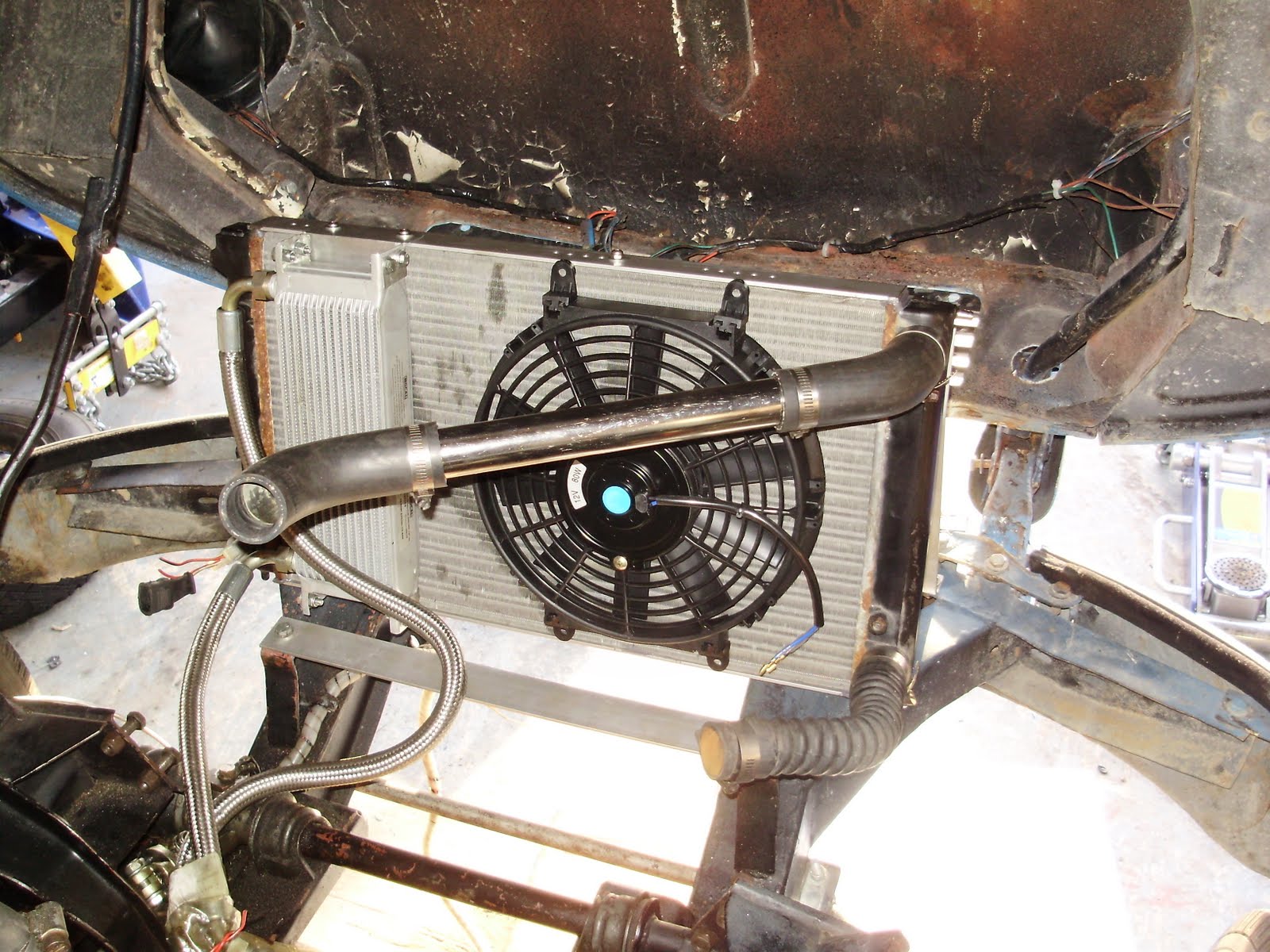
To mount the fan to the rad and to mount the rad to the frame and give it some rigidity I added two 1.5"x1/8" strips of aluminum to the top and bottom of the rad. I pre-drilled and tapped a series of holes in the strips before permanently fixing them to the rad with JB weld.

I mounted the fan by using a pair of brackets made from some thin alloy. One for the top and one for the bottom. I also made a pair to allow me to mount my oil cooler on the rad as well however it is not installed right now as I am waiting for an external oil filter mount kit and thermostat.


I mounted the front of the rad by bending a pair of braces from 1"x1/8" aluminum and using existing holes on the frame. The rad was attached to these using the stock holes and screws.


I plumbed the stock VW Golf expansion bottle with the top hose being connected to the top air bleed on the rad and connected the lower outlet to an addition port on the lower pipe.


This lower pipe was the only part of the cooling system which had to be made. I took a piece of 1/2"OD aluminum piping which was left over from the Megajolt installation. I flared one end of it using a 3/8" drive socket which tapered and fit nicely inside. I them drilled a 1/2" hole in the vacuum tube and made it slightly oblong so that I could push the 1/2" pipe through from the inside. This way the flare will make sure that enough if the JB weld cracks, the section of pipe stay connected. It will also transfer some of the load better. I sealed the joint with JB weld, allowing it to dry for two days.


All of the rad hose bends were from a single S shaped section of 1-1/4" rad hose which I found at a local parts supplier. Now your probably wondering how you make that crazy turn to the right for the rad inlet as it used to be on the left. I just turned my thermostat cover 180deg which worked perfectly with the bends of rad hose I had, however I plan to turn it back and use a swirl tank from merlin which will purge the air better and make a nice 90 bend at the same time. This would also replace the VW expansion tank as the swirl tank has it's own pressure cap.

As of right now the system is working perfectly with the air being slowly purged into the expansion tank and the fans coming on automatically.


Stay tuned for more details on the swirl pot plus an updated schematic which includes a fan operation light and PDF templates for the bracket to mount the fan(s)

March 16, 2011

Golf Rad Conversion Finished

Well the rad is in and topped with coolant. It is not 100% done as I plan to add another air return from the thermostat cover. I only needed to make one custom piece in the whole system. A bleed tee on the pump suction side. I flared the take off and inserted it into the hole from the inside of the larger tube, this way the JB weld is only used a sealant and is not really load bearing. 
You can see the custom piece as the lower line in the picture below. Notice that the pump will circulate coolant through the expansion tank however the air return side has a built in restriction <1mm diameter so it will be a relatively slow circulation. Also notice that I was able to get a nice line by just flipping the thermostat cover 180deg. Not perfect but it works and everything clears.
Here is the whole engine back in the car with the dizzy in place for now to set up the carbs. I want to get all systems go before switching to the Megajolt. That way I'm not trying to tune the carbs and troubleshoot the Megajolt at the same time. Small steps, keep them simple and get them right.
The Megajolt bodge. Added a pair of spacers to move the VR sensor out and allow me to mount the trigger wheel on the outside of the pulley for now. I am going to order a smaller wheel from boost in the future and return to the position behind the wheel.
Posted by Picasa

February 15, 2011

Rad Conversion Hardware DONE

The fan arrived today so I finished up the mounts for the fan and for it mounted. Under the hood is looking pretty tatty though so I will have to work on that.  Now if I could only put an engine in the big empty space behind the rad. 

I'm going to need a longer flex hose from the lower outlet to the pump for sure though. 


February 13, 2011

Rad again..

I really should stop making posts until the end of the day so there wouldn't be so many. The epoxy has cured and the top and bottom cooler mounts are done. Fit was perfect. I love Solidworks sheet metal tools. Again just printed a pattern full scale, cut it out, bent it installed it. 

I am going to need a longer lower rad hose however as I don't think the stocker is long enough. Darn.

Radiator Conversion Progress

I made one last change to the rad design and that was to add 2 extra holes on either side of the original holes in the top and bottom additions to the rad. The idea was to add some adjust-ability to the fan and cooler positioning. The holes are spaced 1/2" apart giving me and inch of movement left or right. I finally got around to updating the spitfire frame model with numbers from the workshop manual. 


 I also crawled under the car and was able to sit up under the hood between the frame rails (where the sump usually resides). It worked out awesome, I was able to play with the rad position and found that there was a ton more room than I initially thought. I plan to mount the rad using this same method so I can get it in the best possible position. right now it's looking like about 80deg angle to the rails and about halfway around the further forward bend in the frame rail. Once I get it mounted I'll make some cardboard templates to make a cowl for the sides and bottom.


My elbows and length of pipe are set. I just need the engine back in the car to finalize the length of the pipe. Should work perfectly with a GT6 thermostat cover. I still need to locate a header tank. Perhaps a trip to the wreckers for a cheap plastic one for now.
Here is a closeup of the 10-24UNC holes in the upper(mirrored on lower) mounting rail. These were all drilled and tapped on the bench and have now been JB welded to the ends of the core with a couple of globs bid way for extra support. Aluminum is 1-1/2" x1/8" which I bought in an 8' length for cheap from Princess Auto. Just waiting for it to dry so I can work on the cooler mounts and rad mounts.

February 8, 2011

Rad Design Changes

While i was waiting for the UPS guy I decided to mock up the rad and cooler with the hoses to make sure the components would fit together. My main worry was the alignment of the fittings on the cooler hoses would bind and put stress on the cooler fitting. Glad I check they undoubted would have. The only way around this is to have the hoses enter the cooler from the drivers side. I decided to make the system more modular. I will add a 1/8" or 3/16" x 1.5" strip of aluminum to the top and bottom of the rad. This will have several tapped and threaded holes in it to suit the fan and cooler locations. the aluminum sheet metal parts appear blue in the images and the bronze colour is the additional strips. Mount this way also gets away from the spacer tubes on the cooler and saves a ton of weight. 

February 7, 2011

Radiator Conversion Thoughts

The great part about being fluent in the world of CAD/solid modelling is that you can quickly model all of the parts, align them how you see fit, then create all the brackets from sheet metal without struggling with keeping the parts in position. AND you can just print out the drawings of the flattened sheet metal parts to scale, cut them out to check fit, then trace them as a template. 

My latest train of though is to mount the oil cooler on the left side and the fan in the middle of the remaining parts. The only downside is the this will put stress through the cooler which I know can't handle much. As a solution I plan to put spacers in the end sections of the cooler mounts and run long bolts right through the cooler and it's mounts.  

NO the fan is not actually blue.


Here is a view of the flattened mounts, I am just waiting for the fan to arrive so I can have the exact bolt locations for those two brackets. The cooler bracket(far left) is completely done. I plan to make everything out of 12 gauge aluminum. 
Here are the folded components all on their own.


Next steps are to work on the from mounts and how I am going to attach the rad to the frame. My current plan of attack is to use the 4 holes on the front, attaching them to the sides of the shroud. I will have to use my last model of the frame and hood to work out the final shape. On a plus side it will be much easier to measure the hoods location relative to the frame with the engine out.

UPDATE
I don't feel like creating another post for this but the side support and angle are finalized. You can see the spacers on the ends of the oil cooler. I also added the hoses to the cooler as well. and mounted on the spitfire frame. How did people survive pre-solid modelling?


I also made the bracket which connects the oil cooler to the header tank out of some 22gauge aluminum just to check the fit. This method of creating sheet metal parts is superb. Perfect fit first time.

February 3, 2011

Golf Radiator Conversion


The 90-92 Golf Radiator has two 1-1/4" inlet and outlet both positioned on the left hand side with a spacing of 10.25" between them. This causes some difficulty as the spitfire thermostat cover exits to at a 45deg angle to the left of the motor. To overcome this temporarily I will be using a GT6 valve cover which allows two advantages.
  1. The outlet exits straight to the front of the engine
  2. The cover has a second, smaller, outlet which I will connect to the header tank to allow proper filling of the cooling system and air to escape.

GT6
Thermostat Cover


The lower outlet's location is not a problem as it feeds the pump and the flex hose can easily accommodate it.

On the lower left hand header tank is a fan control switch. The stock wiring diagram for a car w/o AC is as follows

The switch has two settings, the low speed of the fan switches on at 95C and the high speed switches on at 105C. The two speeds are controlled by a resistor at the motor. The fan I have ordered does not have a resistor wired in. I am considering two options:
  1. Put a resistor in line to give two speeds to the fan
  2. Buy a second, possibly smaller fan. I would then connect on fan to the lower temp and the second fan to the higher temp. This way the second would come on for those extra bad days.
The first fan I am going to use is a 10" unit off ebay. The fan is capable of moving 1200cfm and is rated at 80W


More Details Coming Soon!

August 17, 2010

Rad/Cooler Mount v2.0

This version was built and fitted to the car, although with a bit more than the 10deg pictured here. The local supply had a Z bend rad hose which fit perfectly in the more angled design. The two were combined and the result seems to be a good fit. The real test will be the drive to work. Pictures to follow.

I am very pleased with how the cooler mounted up in the final product. the hoses fit nicely and don't touch anything bar the fittings.
Posted by Picasa